Friday, December 22, 2006

Ever wonder how to create a cut and fill shade??

I get this question all the time when I am conducting C3D training. Calculating the earthwork quantities or volumes is pretty straightforward task but most engineers would like to see the extent of cut and fill being reflected on the drawing itself. How to do it? It’s quite easy actually and what I did was actually to manipulate the surface’s styles that come together with C3D templates. (I strongly urge those who are using C3D to use the existing templates in C3D handsomely…especially the 2007 version. It is very comprehensive and it also provides those who are just starting out with C3D a little clue about styles and setting). Sorry, I have digressed from my topic. Anyway, to begin creating your cut and fill shades in C3D; these are the steps that recommend:

1. Make sure you have two surfaces created for comparison; i.e. an existing surface and proposed surface in C3D.
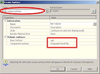
2. Next, create a new volume surface. There two methods for volume surface which are TIN volume or GRID volume. Choose either one and select your surfaces appropriately as shown in the diagram below:

3. Notice that when you hover your cursor (crosshair) over your Volume Surface, it will give you a +ve or –ve values depending on whether the area yield cut or fill as shown.

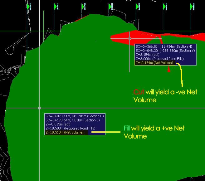
4. Once you have your Volume Surface created, you can begin to generate the Cut and Fill shade. In order to do that, you’ll need to go to the surface properties and choose the Elevation Banding (2D) (provided if you’ve created your drawing via the _Autodesk Civil 3D (Metric) NCS Classic template). Buzz me if you need illumination.
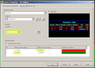
5. Subsequently, go to the Analysis tab. Choose only 2 ranges and click on run analysis. Change the Maximum Elevation values for ID no. 1 to 0 and the Minimum Elevation values for ID no. 2 to 0. 6. Click ok and you’re done. You might observe that at times your surface doesn’t mirror the surface you have in mind. Don’t fret, make use of the edit features under the surface properties i.e.; you can add Boundaries to show only the extent if your working area, cut/fill only…etc.
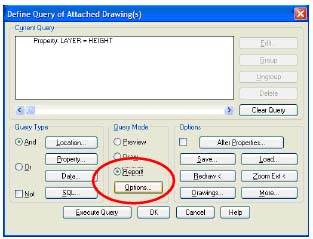
7. Last but not least, I have some engineers who came to me and ask whether C3D can generate the Cut and Fill shade in hatch pattern instead of hatch solid. Well the there is a workaround. The good thing with C3D is it comes together with AutoCAD and therefore it has the best of both worlds. What you need to do is to export the completed drawing to AutoCAD (File>Export>Export to AutoCAD)
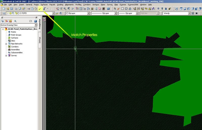
8. Open your drawing using Civil3D as AutoCAD and you’ll notice that the solid hatch representing the cut and fill is not in 1 piece. This is the tedious part. You’ll need then to edit the hatch solid to another hatch pattern of your choice and inherit the properties using Match Properties. It’s not that hard after all…
Happy trying.

Wednesday, December 13, 2006

Converting 2D Text to 3D Points

There are several ways to input data; here in Malaysia, the most common data used are survey points (also known as spot heights) and contour lines. However, before creating a ground surface, you should try to clean the data up as much as possible so that you have less editing work later.

It is common to receive a 2D drawing which only contains the text representing the elevation of each spot height; i.e. there are no points with elevations. In this case, we must create 3D points at each position. Autodesk Civil 3D is able to automatically create 3D points for you based on each text value that represents the elevations for the points.

The conversion process is very simple: first, you need to generate an XYZ file from your drawing, after which you will import the file into Autodesk Civil 3D.

Verify The Drawing Data

  1. Open the drawing containing the spot heights in Autodesk Civil 3D. If you had received the drawing from an external source, copy it to your project’s dwg folder first before opening it.
  2. Check the drawing to see where and how the points and/or text information is stored. They are typically saved in separate layers.
  3. If your drawing already contains 3D points, you don’t have to convert the text into 3D points; you can straightaway use these points to create your existing ground surface. However, be sure to check that these 3D points are placed at the correct elevations.

Note: To check if the points are in 3D or not, use the Properties Window and check the Z value of each point against the relevant text.

  1. If your drawing only contains the text values, note down the layers which contain those text.

Creating The 3D Points

  1. You cannot create the 3D points directly from this drawing, so create a new drawing or open a blank drawing (for example, the survey.dwg created from the previous chapter).
  2. If your Toolspace is not already open, open it from the menu General > Show Toolspace…


  3. In Civil 3D interface, click on Map > Query > Define Query…
  4. In the Define Query window, click on Drawings and click Attach.
  5. You can browse directly to the folder containing your drawing, or you can use aliases.

Note: Using Aliases
Aliases in Autodesk Map is a shortcut to your folder. This is extremely useful when you need to access a folder in Autodesk Map often.

To create an alias:

  1. Click the Create/Edit Aliases icon.
  2. In the Drive Alias field, type in a name to identify the folder you wish to create a shortcut to. The name must not have any spaces in between.’
  3. Click Browse and browse to the folder you wish to create a shortcut to. Click OK.
  4. Click Add. You should see your new alias in the box above.
  5. Click Close when you are done.
  1. In the upper panel, select the drawing which contains the text values which you want to convert into 3D points. Click Add. You should see the file added in the lower panel.
  2. Click OK. The drawing name will be attached in your Toolspace.

Before you start converting your data, first you need to filter out all information to ensure that only the text values containing the relevant elevation data will be converted. You wouldn’t want text containing words like “Tree” or “School” in your point database! To filter out the data, you would be using Queries.

  1. In Civil 3D interface, click on Map > Query > Define Query…
  2. In the query window, filter out the data by using the options under Query Type.
  3. Typically, Property is used as the text values are often placed on a separate layer. Click Property.
  4. In the Property Condition dialog window, click the Layer radio button. In Value, you can type in the layer name, or you can select from a list. Click the Values button. You will see a list of all the layers from your attached drawing, from which you can highlight. To select more than one layer, hold down the Ctrl button while you click on the layer names. Click OK.
  5. Check the information, and click OK.

  6. Before running the conversion, run a quick check to ensure that all the data has been filtered properly. Under Query Mode, click Preview, and then click Execute Query. (Note: If you select OK, nothing will happen as it will merely save the query settings; it does not actually run the query)
  7. You will see a preview of all the data in your drawing. You can still zoom and pan the drawing to view the data, but if you redraw, the data will disappear. Take a look at your drawing to make sure that the data has been properly filtered.
  8. Once you have verified that the data has been filtered properly, you can run the conversion now. Go back to the Query window.
  9. Without modifying the query settings, under Query Mode, select the Report radio button, and click Options.
  10. This is where you specify your report template, i.e. your XYZ file. Click Expression.
  11. In the Report Template Expression window, open the Properties tree. Scroll downwards until you see X1. Highlight it and click OK.
  12. Click Add. You should see .X1 added in the top panel.
  13. Repeat the above steps to add Y1.
  14. For the last column, don’t select Z1! This is because the Z-value in the drawing is 0. Instead, you would be making use of the text value as the elevation. Repeat the above steps to add STRING.
  15. Click the Browse button, and type in the name of the XYZ file you are going to generate.
  16. Click OK, and then click Execute Query. The XYZ file will be generated.
  17. You can check your file by opening it from Windows Explorer.
  18. To import the points, go to the menu Points > Create Points > Import Points.
  19. Under Format, select ENZ (comma delimited) from the drop-down list.
    Note:

The drop-down list contains a list of standard file formats in Autodesk Land Desktop. You can easily create your own format if you need to.

P = Point Number
N = Northing
E = Easting
Z = Elevation
D = Description

Comma delimited means the columns are separated by commas, whereas space delimited means the columns are separated by spaces.

  1. Under Source File, click the open icon, browse to the folder containing your XYZ file, and select the file.
  2. Check the Add Points to Point Group, and click the blue icon on the right. Create a point group named Existing. This is to make it easier for you to create your existing ground surface later. By naming your point group Existing, you will know that all the points in this group are meant for your existing ground surface.
  3. Click OK.
  4. The points will be imported into the drawing.
Original text by Hoo Sze Yen and was originally meant for Land Desktop. She is generous enough to allow me to publish this. Thanks pal. Imagine if you have to manually edit those texts ???? Thank God for technology.. ;-).

Introduction of Civil 3D

I suddenly feel an urge to start blogging on Civil 3D (Civil Engineering software by Autodesk). I hope to share and exchange my knowledge about Civil 3D at least in Malaysia. You can find that this is not new in the west but definitely something to chew on at least for a start in this region.

I've been using Civil 3D since 2005 and it has been such a great tool for me as a Design Engineer. I guessed this software is gaining its momentum since its inception in year 2004. I hope to contribute in one way or another especially in the local scene.

For a start, let me share with you my knowledge on Civil 3D. Civil 3D is a powerful civil engineering software developed by Autodesk. As the name implies, it provides comprehensive solution covering various infrastructure works namely earthwork, subdivision, highways, land development, survey, drainage as well as in areas related to project management. One of the capabilities of C3D is its ability to dynamically link objects created in it. Any changes or revisions to the design will be updated almost instanly by a click of mouse. Integral to this capability is it save you a lot of time as well as give you more time to consider different scenarios. Believe me, I really appreciate this function. No one likes revision and you cannot avoid changes in engineering. How would you like to cope with changes when you are already bogged down and have tight deadlines to meet? Sound familiar? As an engineer, it is my responsibilities to consider all possible options and optimize the design. Civil 3D helps me to focus and spend my energy on my design. I can get a balance earthwork design easily and my boss is happy about it.
Drafting process has also been made easy with the use of Styles. Phew! Now I can apply different template for different clients as easy as ABC.


I will post some useful tips on converting 2D texts to 3D points in my next post (courtesy of Sze Yen- she taught me how to do it) which is a very familiar scenario in Malaysia. I welcome any comments.