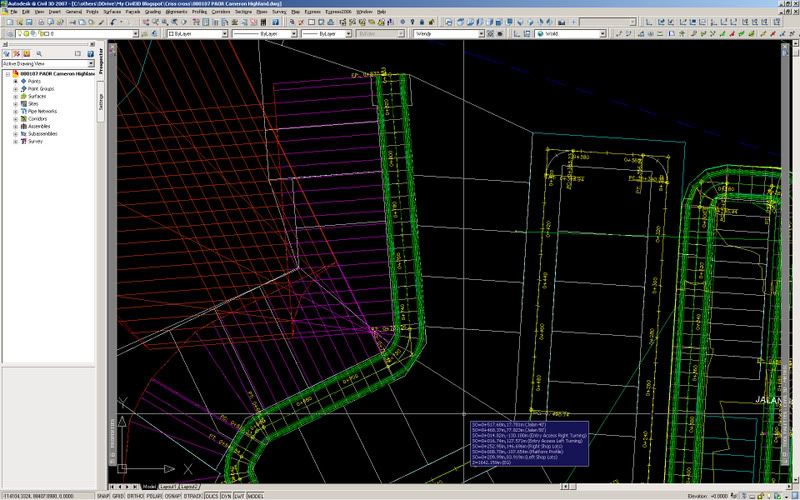
 I was exasperated when the above happened. Thank God for assembly offset…I managed to do some workaround although my road model isn’t dynamic (which defeats its purpose), I figured that it’s better than having to manually do it and I obviously don’t have the luxury of time to do it. I apprehended that the rationale the corridor model is giving me a criss-cross results when the curve is converging is mainly due to the fact that the assembly continues to surge upward to find the target surface perpendicularly. I figured that I have to apply an assembly offset so that the subassembly component (such as a bench) remains parallel to another component (such as the daylight), but said component is not parallel to the main baseline (as in the case of a daylight bench), then an offset subassembly must be used to accurately model the corridor in this region. In order to do this, I used a generic link, in this case LinkWidthAndSlope for each slope as shown in the figure below:
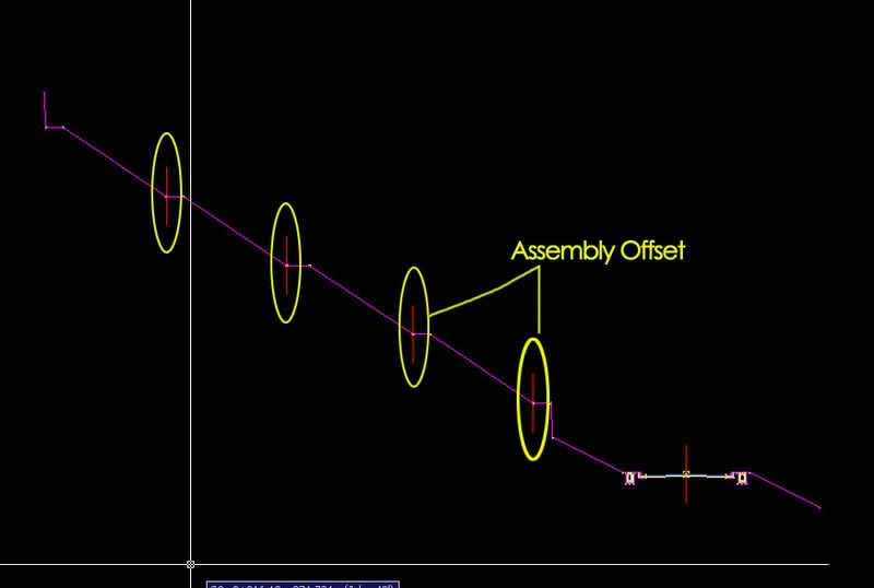
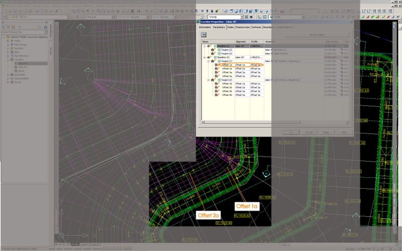
Now, this is the tricky part, you then need to relate the assembly offset to an alignment (offset) which will reflect the correct profile and distance. Before I go any further, I guess some of you might already be thinking out loud how to get those offset alignments? There is an easy way to create those alignments from the corridor model. That means you will need to model the corridor first before applying the assembly offset. In order to do that, go to Corridors>Utilities>Alignment from Corridor. Make sure the conversion option Create Profile is checked. By doing this, you will have both your alignment as well as the matching profile. You'll need to reiterate this according to the numbers of bench for that particular site.
The Offset should then be set to hold the alignment along the toe of slope along the edge of the generic link of the bench as shown:
 Do remember to set your target alignment as shown:
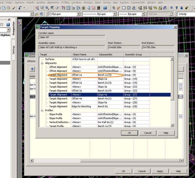
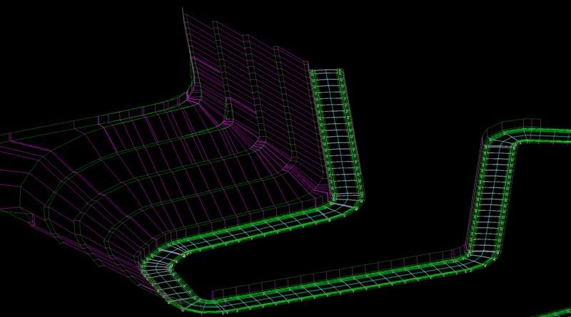
Once you are done, just continue to add the assembly offset and repeat the steps above until you meet the numbers of bench you need. The completed corridor should look something like this: