Sunday, December 23, 2007

C3D and Google Image

Been lazing around in Costa Coffee, Bahrain. I've been travelling quite a bit for the past few months. As I was sipping my mocha, I thought about updating my blog. It was 6 months ago since I updated it...these few months were exhausting and really WORK took a toll on me, physically and mentally but I enjoyed it anyhow. There have been quite a drama in my office lately but I guessed I’ll just have to agree that “Ignorance is BLISS”.
I’ve been doing a lot of river engineering work lately. The approach is based on the use of Geographic Information Systems (GIS) - Civil 3D, a hydrologic model-HEC-HMS and a hydraulic model-HEC-RAS.
I normally start with survey data or some digital spatial data in GIS and use it – by means of the GIS-based application (C3D) – to delineate watersheds and develop watershed parameters for hydrologic modeling – in this case HEC-HMS. After adding precipitation data, I run the hydrologic model and determine the flow values corresponding to different amounts of rain fallen in a given area. These flow values can be then entered into the hydraulic model – in this case HEC-RAS – to generate water elevation values. In order to input the river and surrounding geometric data into the hydraulic model, the geometric information is extracted from a very detailed digital representation of the terrain in GIS. The application used to link GIS and HEC-RAS is called Steltmen. Steltmen extracts the information contained in the TIN, exports it into HEC-RAS, reads the results of the hydraulic model and represent the flooded areas. Computer models are definitely cutting the time and easing the process.

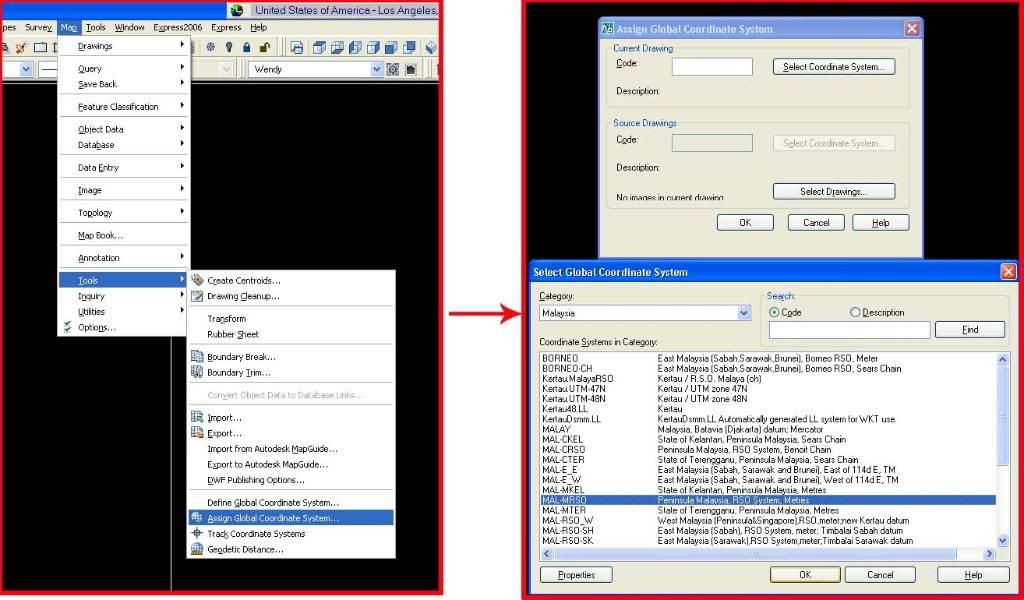
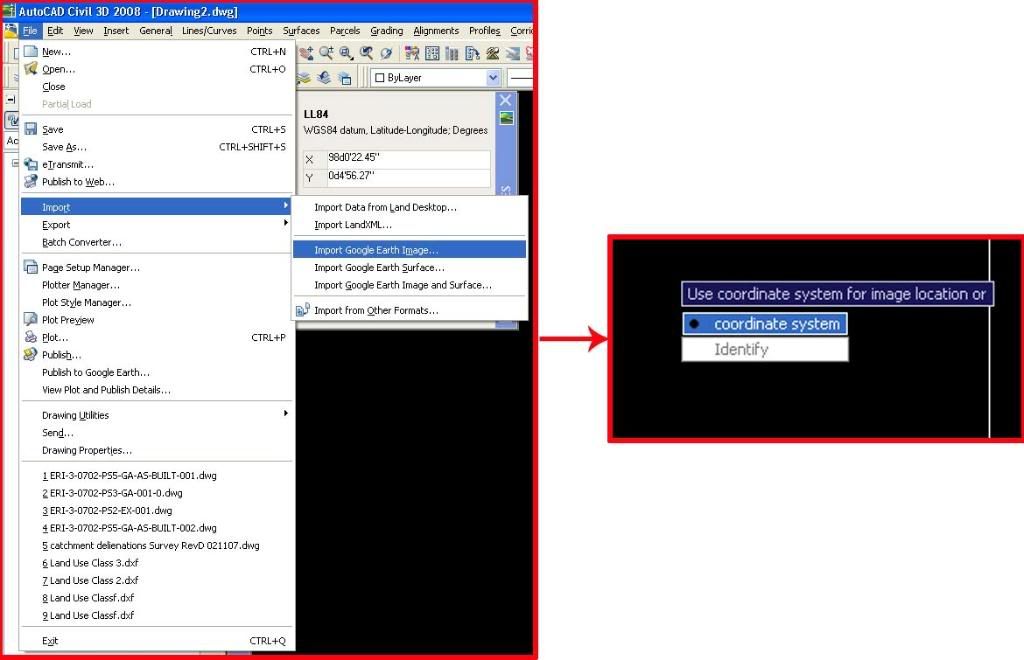
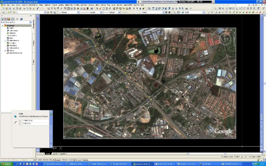
IN this post, I’d like to share a trick I used to import google image into C3D. We all know that C3D 2008 allows us to import google image into C3D provided that you have defined the coordinate system. This is definitely a great tool which I deployed extensively in the course of my work. However, the image imported is in grayscale which isn’t so neat. I figured a way to import the image in color. First, you need to have both your AutoCAD C3D and google earth launched…the following images are self-explanatory…

Photobucket'>
Photobucket
Photobucket
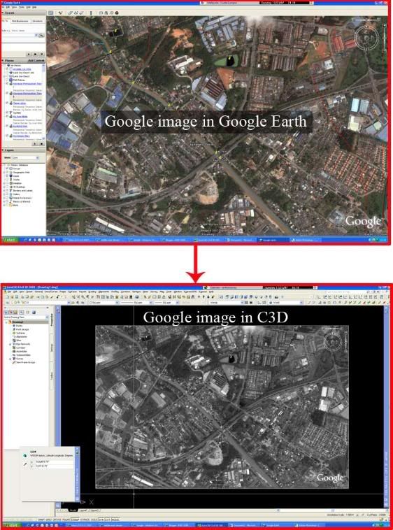
Then, save the image as JPEG in Google earth at the exact position.
Photobucket'> Photobucket'> Photobucket
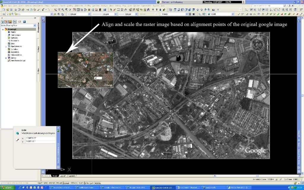
This is really easy and if you need a higher resolution, you can zoom in to the location of interest and repeat the steps above. How cool is that!

Friday, May 4, 2007

tHe BEAUTY of CoRRIdor


I have been really busy for the past few months. One submission after another. I have just completed another mixed development project relying solely on corridor feature. I must say that I am pleased... This is the result..


Friday, April 13, 2007

C3D HURDLES...

I was reading Mark Scacco's post this morning and I can't help but find myself in total agreement with him on his latest posting which titled Top 5 Civil3D Implementation Obstacles.
Management is feeling the pinch and end-users are finding it hard to catch up. I must say that I am among the few whom is fortunate to have the passion to learn C3D since its inception but I am frustrated and disheatened at the number of users in Malaysia. :-(
I wish I can tell the other users the benefits of C3D. My company just renewed the subsription this year and I am really looking forward to use the latest version but how about the others? I see huge potential here and I can only hope that there're more support here....

Friday, March 30, 2007

What to do if C3D crashes after performing a grading??

I am mulling over whether to publish this topic on Grading. I have been blogging about grading and I felt that it is only apt for me to give some tips on grading before I close this chapter. The best thing about the grading feature is its simplicity. It is straightforward and usually works very well with simple feature lines. However, this is not always the case in civil engineering. Have you ever notice that if you create a feature line from surface with intermediate grade points, it'll usually becomes unstable? I figured that it depends on the number of vertexes (intermediate grade points) that is created from the process. The more grade points/vertex your feature line contains, the likelihood for it to crash is higher. What to do if it crashes?
This method is by no means discounting the benefits of grading. I still need the slope scheme that comes with it afterall. Let's look at the illustration below:
What am I supposed to do? I proceeded by using stepped offset instead as shown:

I got the result which is sufficient for me to generate my proposed surface but how about the slope scheme? I for one copy the feature line/3D polyline and paste it into a new drawing. Next, I simplify it by reducing the numbers of vertex but make sure you don't compromise on the accuracy. Then, try to the grading again. Remember, the main purpose of doing this is to get the slope schemes as you already have your projected line from the stepped offset function.

You then need to explode the slope because as alluded to earlier, the program crashed due to grading instability, thus you'll need to dissociate the grading component from the drawing. Note worthy of mention is that it is always a good practice to purge and perform audit check on the drawing to fix any errors within the drawing you are working on. I know this is a temporary measure and I've seen the sneak preview of C3D 2008 which has enhance the grading features considerably. Do click on the link to watch the webcast : https://www.livemeeting.com/cc/autodesklearning/view?id=Civil_RO-49&pw=Audience&cn

Meanwhile, I hope this post will benefit those whom are still using the older version. Cheers!

p/s: Click on the image for larger view

Saturday, March 17, 2007

Grading in C3D 2008

I really like the grading feature in C3D... my wish list for 2008 is that I truly hope that the stability will greatly be improved. As most of you will agree, the feature is really amazing, only that it usually works for simpler feature line/3D polyline. Anyway, it's still a great feature considering the design and drafting capabilities it does. You can always manipulate it by using the stepped offset function in the Grading menu. The only set back is that it's without the slope scheme. :-(
Well, recently, I've the avenue to view some of the videos that showed some interesting enhancement to the latest C3D version. One of it is the C3D Grading feature. Some of the developments are:
  • Broad set of tools for creating and modifying 3D geometry (feature lines, 3D plines, 2D plines, and lot lines)
  • Calculation of feature line statistics such as linear total
  • Usability enhancements to streamline creation of grading features

It does sounds a bit technical right? I for one am not so concerned about these jargons...only keeping my fingers crossed that AutoDesk Team has come up with a yet better solution. I shall be posting an alternative solution for grading should it crashes. I am anticipating to get my hands on the new version and then I can really make a comparison...

Thursday, March 8, 2007

Creating profile from file

I came across the create from File under the Profile menu quite often but like most of you out there, I just couldn't be bothered until recently. I have a chance to work on a drawing which already have preliminary profile levels on the horizontal alignment. More often than not, I will create the profile by layout and insert the PVI's using the conventional method. Little did I know that you can actually create your profile from an ASCII file or a txt file. The advantage of this is that it is faster to import the profile from an ASCII file when you have a fix levels that cannot be altered, i.e, existing road, channel, etc
If you have an ASCII file, just make sure that the format of the file is space delimited as follow:

The first column is the station/chainage while the second column is the elevation of of the particular station/chainage. Just make sure that you stick to this format, otherwise you will not be able to import it. It really does come handy especially if I need to duplicate the profile...You can also create it from an elevation editor. Right click on the editor and click on copy all.
Next, paste it in Excel, delete the 1st row and the last 2 columns as shown below:

Make sure you replace the '+' and 'm' sign from the remaining columns. Select the area with numbers and copy it to a notepad:
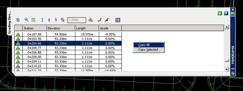
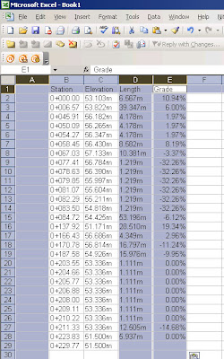
Then, with a bit of editing as follow:Save the txt file and you can start to create you profile from file..


Saturday, March 3, 2007

Civil 3D 2008

I know... I know... I myself am pretty excited about the new release. I figured that some of you might be thinking aloud, Civil 3D 2008? Are you kidding me? It's not even 2008 yet and I am still trying to learn C3D 2007... Well, Autodesk has promised to launch a new version each year and sometimes we're left to wonder what else to expect from the new release... The good news is that C3D can be considered still in its infant stage, therefore you can expect a lot of enhancements... The bad news though is that you will have to keep up and learn faster.
I am expected to get a feel of it anytime soon and I really can't wait to get my hands dirty with this new release. I am keeping my fingers crossed that the grading feature will be more stable and better performance from the 2008 version. Just wait and see.

Friday, February 2, 2007

Criss-crossing in CORRIDOR?

I reckon that no one will dispute the prominence of CORRIDOR modeling in C3D. It is a very powerful function to enable you to model a road, channel, river, grading…etc. However, I was kinda disappointed when I couldn’t get the result that I anticipated when it comes to modeling near a curve. It tends to give you criss-crossing results and I must say that it is not a pretty sight. This usually happens when I am working on a hilly site and it involves using benching assembly. This is how it looks like:
I was exasperated when the above happened. Thank God for assembly offset…I managed to do some workaround although my road model isn’t dynamic (which defeats its purpose), I figured that it’s better than having to manually do it and I obviously don’t have the luxury of time to do it. I apprehended that the rationale the corridor model is giving me a criss-cross results when the curve is converging is mainly due to the fact that the assembly continues to surge upward to find the target surface perpendicularly. I figured that I have to apply an assembly offset so that the subassembly component (such as a bench) remains parallel to another component (such as the daylight), but said component is not parallel to the main baseline (as in the case of a daylight bench), then an offset subassembly must be used to accurately model the corridor in this region. In order to do this, I used a generic link, in this case LinkWidthAndSlope for each slope as shown in the figure below:
Now, this is the tricky part, you then need to relate the assembly offset to an alignment (offset) which will reflect the correct profile and distance. Before I go any further, I guess some of you might already be thinking out loud how to get those offset alignments? There is an easy way to create those alignments from the corridor model. That means you will need to model the corridor first before applying the assembly offset. In order to do that, go to Corridors>Utilities>Alignment from Corridor. Make sure the conversion option Create Profile is checked. By doing this, you will have both your alignment as well as the matching profile. You'll need to reiterate this according to the numbers of bench for that particular site.

The Offset should then be set to hold the alignment along the toe of slope along the edge of the generic link of the bench as shown:

Do remember to set your target alignment as shown:

Once you are done, just continue to add the assembly offset and repeat the steps above until you meet the numbers of bench you need. The completed corridor should look something like this:

p/s: Click on Pictures for Larger Views.


Wednesday, January 31, 2007

Successful Habits

“However mean your life is, meet it and live it; do not shun it and call it hard names. It is not bad... it looks poorest when you are richest. The fault-finder will find faults, even in paradise. Love your life, poor as it is. You may have perhaps so”
Henry David Thoreau

I am currently reading The Seven Habits of Highly Effective People by Dr. Stephen Covey. I must say that I find it satisfactory when it comes to self-improvement or religious book. It speaks to me when he mentioned about freedom to choose your state of mind. You can choose to be a victim of situation and blame the situation because of the conditions you are in OR you can choose to react positively to the situation you are in by telling yourself I am in control of my own feelings; my mood is not dependent on the weather, my colleagues, my workplace...etc... I used to be governed by my feelings a lot. I realized that it doesn't help at all to be negative and whine all day long. I have learnt that each and every one of us is responsible for our own action. Here are some excerpts from the book....

7 Successful Habits

(a la Dr.Stephen Covey)


Habit 1: Be Proactive: Principles of Personal Vision
Habit 2: Begin with the End in Mind: Principles of Personal Leadership
Habit 3: Put First Things First: Principles of Personal Management
Habit 4: Think Win/Win: Principles of Interpersonal Leadership
Habit 5: Seek First to Understand, Then to be Understood: Principles of Empathetic Communication
Habit 6: Synergize: Principles of Creative Communication
Habit 7: Sharpen the Saw: Principles of Balanced Self-Renewal

p/s: For those of you who is just trying to use C3D, or has been using it for quite a while and feel disheartened, try this approach. Instead of finding the software difficult to use, try to approach it as though you are trying to teach someone how to use it.... You will be surprise....

Wednesday, January 17, 2007

What if my alignment doesn't begin with Ch 0+000??

First of all Happy New Year to all! It's been a while since I last posted... Have been busy with work as well as training.
We all know that when we design our roads, it might not necessarily have to start with Ch 0+000. Have you ever wonder how to go about it? It's pretty easy actually.
When you first design / create an alignment, you will see the Create Alignment-Layout window. Change the start station to Ch 0+125 (for example) as shown below:
However, if you need to edit existing alignment, don't worry. You don't have to re-create the alignment. Instead, go to the alignment properties>station>change the station to say Ch 0+150.
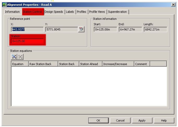
 Hope it helps... My next post shall be on criss cross corridor... sounds familiar???