I've been googling on the web to find out the maximum pipe/structure allowed in Civil3d but I don't seem to be able to find an answer. I did get an answer from a local reseller that the maximum pipe/structure allowed is 500, to which I'm not sure whether it is 500 nos each for pipe and structure or combined number of pipe and structure should not be above 500. In any case, I've encountered errors when the combined numbers of pipes and structures reached 500 or above. The error reads "Unable to apply pipe depth query to current structure. The default structure height will be used."
Figure 1
To be honest, 500 is not much, and the limitation is kinda annoying. I'm working on a very large site and to have the nos of pipe/structure limited to 500 is akin to having a site of not more 4 roads for each network. My site contains the following networks:
Storm network
Sewerage network
Drainage network
Electrical network
Telecommunication network
The planning and coordination of those underground utilities for such a large-scale project was extremely challenging. Therefore, I wanted to have an integrated 3D model which will detect collision points that are almost impossible to detect without such simulation. The site I am working on is about 1,000 hectare (approximately the size of 1,200 of football field). I ended up having about 20 drawings for each zone (the site is separated into 4 zones) of the networks mentioned and not to mention the daunting task of referencing all the drawings together. Yet, I managed to pull it off as it is still faster to do it in Civil3D than the old conventional 2D method.
Back to the earlier question. What to do when you encountered the errors mentioned in Figure 1? Many times, when you reached the limit of 500 nodes, you may still need to refine the design by moving/adding manholes and pipes around. However, when you try to insert a new structure, the structure size doesn't look right and you are not allowed to change the structure part by using the swap part command. The workaround for this is to copy any existing structure/part in the existing drawing and move it to the pipes which it belongs. Then, you will need to reconnect the pipes to the structure. It is tedious but, at least it works and what matters is the end results. You may need to change the values of the invert levels. Once you have completed all the networks, you can compile them into one drawing by using the data shortcuts. Then you can use the interference check feature to detect collision.
As the title suggests, I wanted to know how many of my fellow Malaysians in the AEC industry actually know about BIM (Building Information Modeling)? BIM, although not something new in the US, UK and Europe, it is still in its infant stage in Malaysia. There are local resellers representing the companies behind the marketing of BIM like Autodesk but its lacking momentum. A google search on "BIM Malaysia" proof my point, the BIM word is still very much unknown to the AEC industry in Malaysia. I applaud our honorable Prime Minister, Datuk Seri Najib on his effort on promoting innovation amongst Malaysians, yet, when will the AEC industry here catch up with the BIM technology that has taken the AEC industry to a new height?
McGrawhill Construction defines BIM as: The process of creating and using digital models for design, construction and/or operations of projects, while Wikipedia defines BIM as: The process of generating and managing building data during its life cycle. Typically it uses three-dimensional, real-time, dynamic building modeling software to increase productivity in building design and construction. The process produces the Building Information Model (also abbreviated BIM), which encompasses building geometry, spatial relationships, geographic information, and quantities and properties of building components.
Being a Civil Engineer by profession, I would prefer to look at the word Building as a verb as in "Building" and gathering information that integrates all pertinent data into a model. Some would call it Civil Information Building (CIM); in any case, the gist is that BIM has many tangible benefits when it is implemented correctly. However, the situation in Malaysia is that most civil engineering consultancy firms still adopt the legacy method of performing design, calculation and analyses manually and producing drawings in 2D. Though these methods are great in the early stages of design, it will become a nightmare when there is a change in design. One will have to start doing design and drafting all over again. Although, there are some remarkable and talented engineers who have developed programs to bypass these menial tasks, sadly these individuals either quit or being headhunted into bigger international firm. I myself has often became frustrated in trying to bring changes in the local AEC industry to adopt the BIM technology, to move into vertical products, to convince the management that BIM is just not about producing pretty 3D images for visualization, but its about the information contained in the 3D model which reflects integrated and coordinated changes when design changes. It's also about the culture of the company when the company is not ready to support such collaboration. The situation is sad and it does seems that I will be banging my head on the wall to try to make it work and still have people come up to you saying, its not going to work or worst, the manager expect to see model to be built instantly with a click of mouse!
Creating collaborative teams of Architects, Engineers, Contractors and Managers will be ideal and I will be delighted to come across a local firm whom are willing to go to that path. Perhaps, for the young engineers, they want to avoid the steep learning curve, for draughtperson, the BIM technology seemed rocket science while management aren't ready to invest. Kevin Loader once wrote: "If you're not riding the wave of change, you'll find yourself beneath it"
Civil3D is getting better!. I am loving this new feature in Civil3D 2010. I have been overloaded with intersection design for a large scale mixed development and these tools are GREAT! The downside though, performance gets affected once the file gets larger, I am hoping that Autodesk will release Civil3D 64 bit soon. Here's a video on my latest endeavors... I have used RDV systems to animate the video and it's so easy....
More often than not, we may find the need to edit surface created in Civil3D in 3D studios max for rendering purposes, 3D massing, etc.
There are three methods to create an editable mesh from Civil 3D. Generally, the points that generate the surface need to be displayed in Grid so that the surface can easily be edited using polygonal mesh in max. Expert in Max has told me that this surface display is easiest to edit in Max.
This can be done either by one of the following methods:
Method 1- Using EDITS surface
i. In prospector, right click on Edits and select Smooth Surface... The Smooth Surface dialog appears.
ii. Under Point Interpolation/Extrapolation Output, select the surface as the output region.
iii. Change the Grid X - spacing to 1 and similarly for Grid Y spacing. This spacing is dependent on the density of the mesh you want to see in MAX. The smaller the number (1 being the smallest), the denser the surface will become and this will impact the size of the file which obviously will be large as well.
Figure 1.0
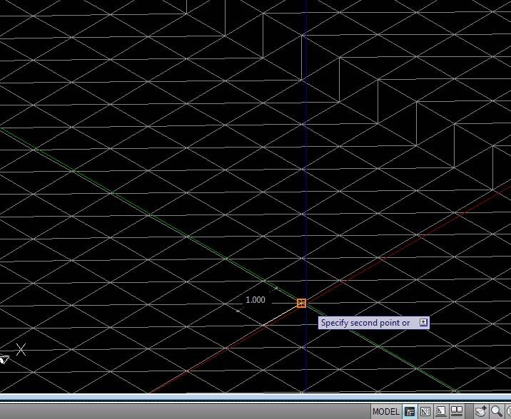
iv. When completed, your surface would have displayed the 1 m Grid spacing as shown in Figure 2.0
Figure 2.0
v. Change the display of the surface to show just points in the isometric view. Create a new Surface style under Surface properties.
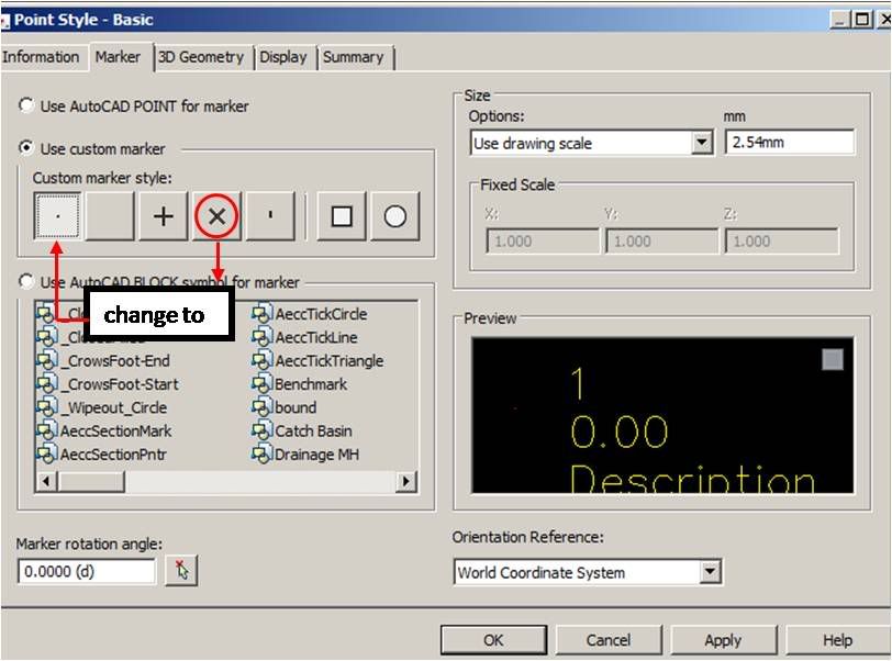
vi. Name it Points. Navigate to Points Tab and change both the +Data Point Symbol and Derived Point Symbol to
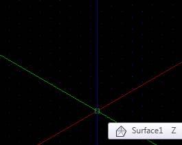
vii. Then, click on the Display tab and change the View Direction to Model. Make sure the only component that is visible is Points.
Figure 3.0
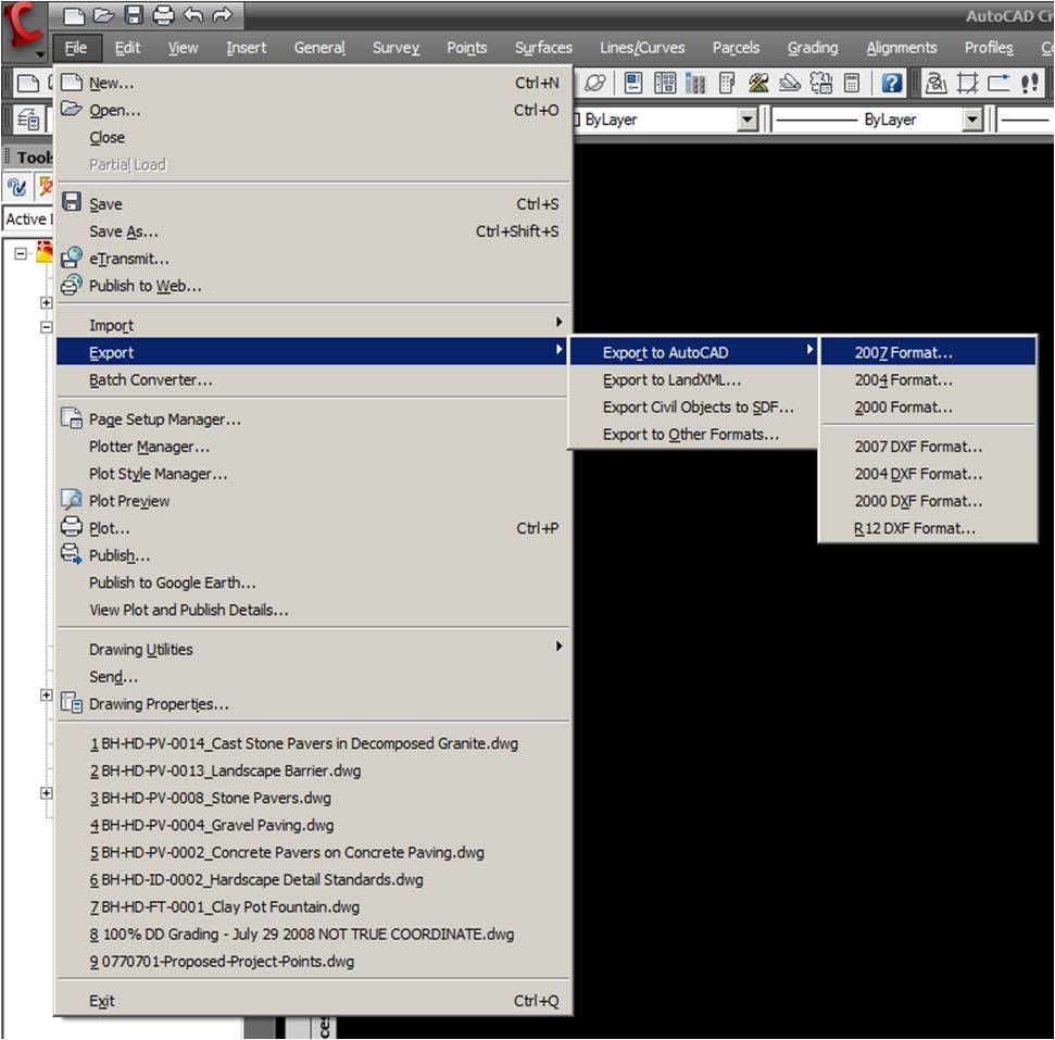
viii. Export the surface to AutoCAD from the main menu, File>Export>Export to AutoCAD>2007 Format as shown in Figure 4.0
Figure 4.0
ix. Import the Exported AutoCAD surface to 3D studio max.
Method 2- Using Civil 3D points or COGO points
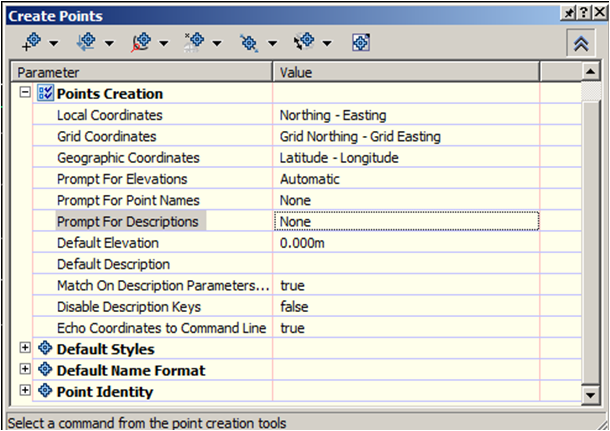
x. In prospector, right click on Points and select Create... The Create Points dialog appears.
xi. Expand the Create Points dialog. Under Points Creation, change Prompt For Elevations to Automatic, Prompt For Point Names to None and Prompt For Descriptions to None as displayed in Figure 5.0
Figure 5.0
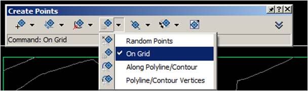
xii.Collapse the Create Points dialog. From the Create Points dialog, click On Grid as shown in Figure 6.0
Figure 6.0
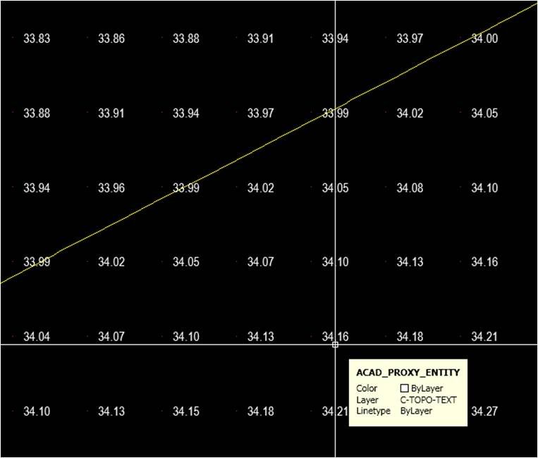
xiii. Select the surface when prompted. At the command-line prompt, pick the lower-left corner of the surface. Press enter or space when prompted to select Grid rotation. Enter the desired spacing when prompted Grid X spacing and Grid Y spacing. Pick the upper-right corner when prompted to Specify the upper right location for the grid:
xiv. When completed, your surface would display the points and elevations as displayed in Figure 7.0
Figure 7.0
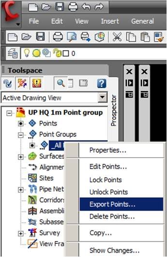
xv.Expand the Point Groups from the prospector. Right click on _All Points and select Export Points... as shown in Figure 8.0
Figure 8.0
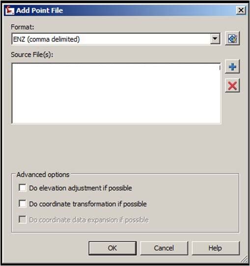
xvi. The Export Points dialog appears. Set the format field to ENZ (Comma Delimited).
xvii. Click the file folder button and navigate out to save the output file.
xviii. Leave all other boxes unchecked.
xix. Click OK.
xx. The above steps (i - x) are to export points in a grid format and to obtain the points in a desired ACSII format. The ASCII format can be in txt, prn, auf,csv, xyz...etc
xxi. Create a new drawing using the _AutoCAD Civil 3D (Metric) NCS Extended Template.
xxii. From the main menu, choose Surfaces >Create Surface. The Create Surface dialog appears.
xxiii. Change the Name value to Grid points, and click OK to close the dialog.
xxiv. In Prospector, expand the Surfaces >GridPoints>_Definition branches.
xxv. Right-click on Point Files and select the Add option. The Add Point File dialog appears.
xxvi. Set the Format field to ENZ (Comma Delimited).
xxvii. Click the Browse button shown in Figure 9.0. The Select Source File dialog opens.
xxviii. Navigate to the Data folder, and select the txt file saved in step vii.
xxix. Click OK.
xxx. Click OK to exit the Add Point File dialog and build the surface.
xxxi. Right-click on Grid Points in Prospector and select the Zoom To option to view the new surface created.
Figure 9.0
xxxii. Export the surface to AutoCAD from the main menu, File>Export>Export to AutoCAD>2007 Format as shown in Figure 4.0
xxxiii. Import the Exported AutoCAD surface to 3D studio max.
Method 3- Using AutoCAD points
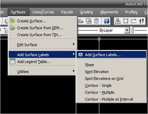
i.Label the surface from the Surfaces menu. Choose Add Surface Labels>Add Surface Labels... as shown in Figure 10.0.
Figure 10.0
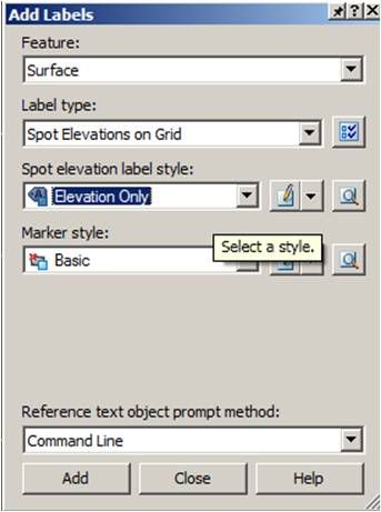
ii.From the Add Labels window, choose Spot Elevations on Grid under Label type:, Elevation Only under Spot elevation label style: and Basic for Marker style as shown in Figure 11.0
Figure 11.0
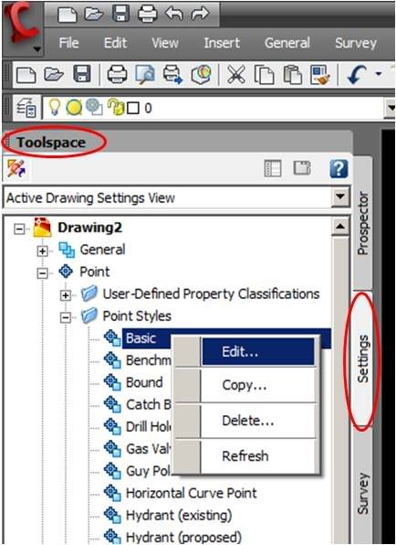
iii. Depending on the size and spacing of the Grids, it will be prudent to change the default point styles to reduce the processing time. This can be done by going to the Settings tab in the Toolspace. Then, change the point style as shown in Figure 12.0 and 13.0
Figure 12.0
Figure 13.0
iv. Click Add (Figure 11.0). At the command-line prompt, pick the lower-left corner of the surface. Press enter or space when prompted to select Grid rotation. Enter the desired spacing when prompted Grid X spacing and Grid Y spacing. Pick the upper-right corner when prompted to Specify the upper right location for the grid:
v. When completed, your surface would display the points and elevations as displayed in Figure 14.0
Figure 14.0
xxxiv. Export the surface to AutoCAD from the main menu, File>Export>Export to AutoCAD>2007 Format as shown in Figure 4.0
xxxv. Import the Exported AutoCAD surface to 3D studio max.
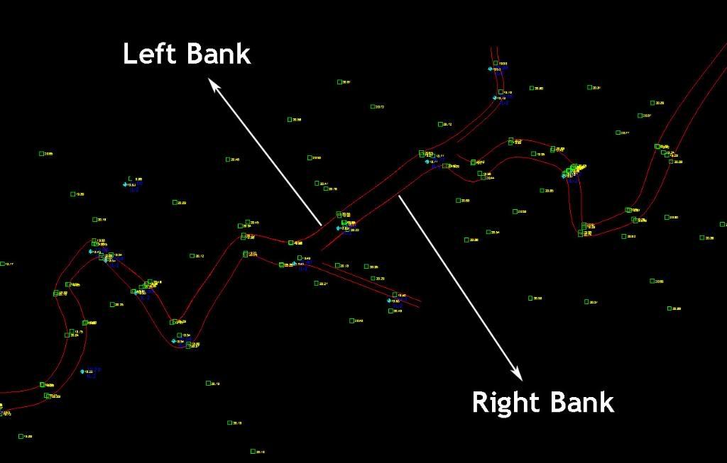
In my previous entry, I mentioned that I have been burying my nose in river engineering works. Here's the sequel to it. Rivers and channels have curves/bends. However, in most instances, channel bends are not accurately modeled due to the dearth of survey information.
This is especially true when the rivers are surveyed using the conventional surveying method. Bends are an important feature as correct and accurate representation of DTM will be used as the geometric data in HEC-RAS (River analysis System) model. Equally impotant are the clear definition of left over bank, right over bank as well as the river bed. To account for those bends, I'd define the right and left banks for the river/stream that I am working on. In most cases, the surveyor would have already defined it either by using spline or polyline.
Make sure the polylines are joined and if it’s a spline, convert it to polyline.
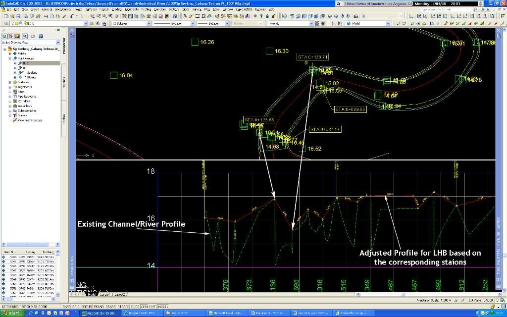
Once, that is done, convert the left and right polyline to alignment. Create profiles for the two alignments. In order to create profile for the left/right bank, label the alignment at the location where the survey has been carried out to display the station/chainage information. Likewise, define a centreline alignment (CL) for the river and create profile using the same method as alluded to earlier. Create two horizontal viewports. One showing the plan and the other showing the profile. Then, create the profile based on the levels and corresponding stations/chainages shown.
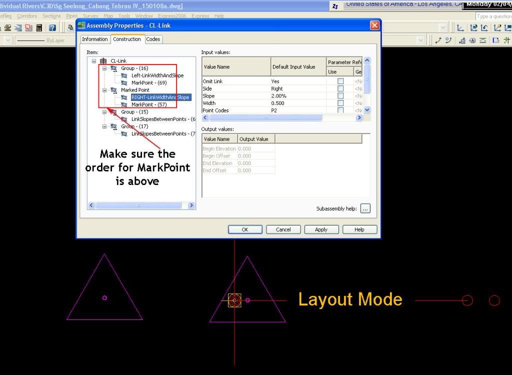
I used a combination of MarkPoint and LinkSlopeBetweenPoints for the assembly. First, insert the LinkWidthAndSlope. Put dummy values for the width and slope since it’ll be controlled by the alignment and profile. Set the omit link to YES. Secondly, add the MarkPoint. Set a name for it, in this case, LEFT. Repeat the same for the right side of the assembly. The assembly should look like this:
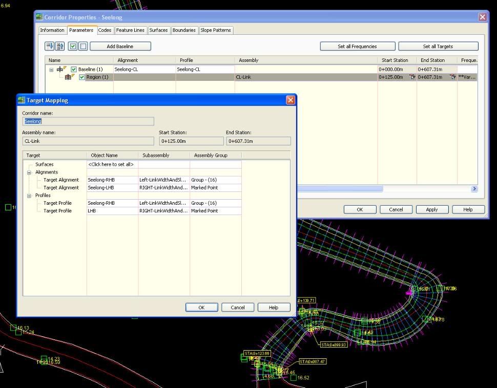
For the corridor, base alignment and profile would be the river CL. Then, set the left target alignment and profile to the left bank alignment. Do the same for the right as shown:
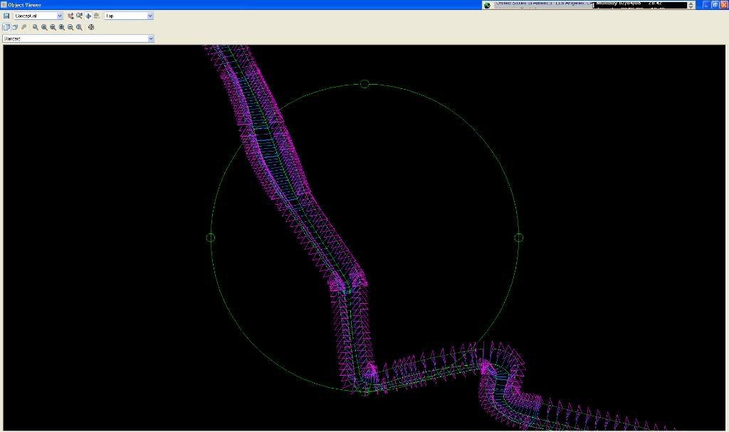
The finished corridor should look like this:
If there are better ways to do it, do let me know.... :-)
Been lazing around in Costa Coffee, Bahrain. I've been travelling quite a bit for the past few months. As I was sipping my mocha, I thought about updating my blog. It was 6 months ago since I updated it...these few months were exhausting and really WORK took a toll on me, physically and mentally but I enjoyed it anyhow. There have been quite a drama in my office lately but I guessed I’ll just have to agree that “Ignorance is BLISS”. I’ve been doing a lot of river engineering work lately. The approach is based on the use of Geographic Information Systems (GIS) - Civil 3D, a hydrologic model-HEC-HMS and a hydraulic model-HEC-RAS. I normally start with survey data or some digital spatial data in GIS and use it – by means of the GIS-based application (C3D) – to delineate watersheds and develop watershed parameters for hydrologic modeling – in this case HEC-HMS. After adding precipitation data, I run the hydrologic model and determine the flow values corresponding to different amounts of rain fallen in a given area. These flow values can be then entered into the hydraulic model – in this case HEC-RAS – to generate water elevation values. In order to input the river and surrounding geometric data into the hydraulic model, the geometric information is extracted from a very detailed digital representation of the terrain in GIS. The application used to link GIS and HEC-RAS is called Steltmen. Steltmen extracts the information contained in the TIN, exports it into HEC-RAS, reads the results of the hydraulic model and represent the flooded areas. Computer models are definitely cutting the time and easing the process.
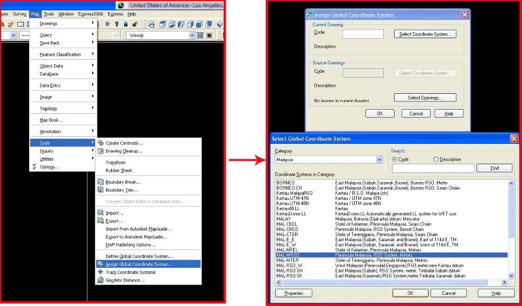
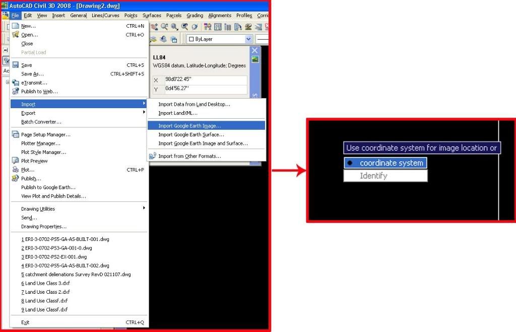
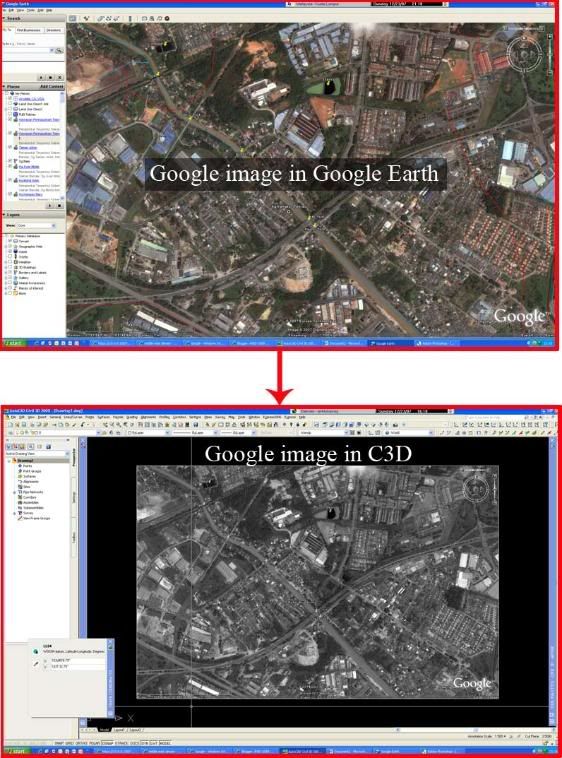
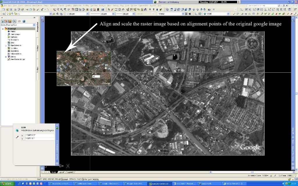
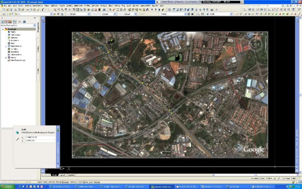
IN this post, I’d like to share a trick I used to import google image into C3D. We all know that C3D 2008 allows us to import google image into C3D provided that you have defined the coordinate system. This is definitely a great tool which I deployed extensively in the course of my work. However, the image imported is in grayscale which isn’t so neat. I figured a way to import the image in color. First, you need to have both your AutoCAD C3D and google earth launched…the following images are self-explanatory…
'> Then, save the image as JPEG in Google earth at the exact position. '> '> This is really easy and if you need a higher resolution, you can zoom in to the location of interest and repeat the steps above. How cool is that!
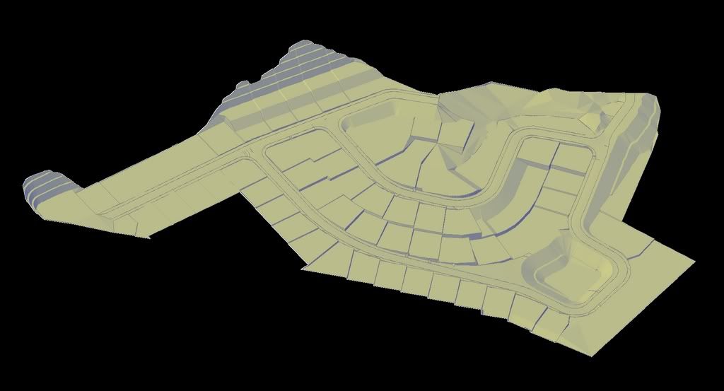
I have been really busy for the past few months. One submission after another. I have just completed another mixed development project relying solely on corridor feature. I must say that I am pleased... This is the result..


 Figure 1
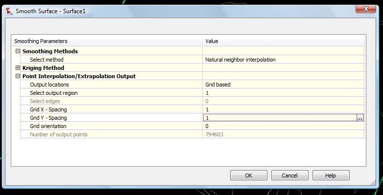


