
It is common to receive a 2D drawing which only contains the text representing the elevation of each spot height; i.e. there are no points with elevations. In this case, we must create 3D points at each position. Autodesk Civil 3D is able to automatically create 3D points for you based on each text value that represents the elevations for the points.
The conversion process is very simple: first, you need to generate an XYZ file from your drawing, after which you will import the file into Autodesk Civil 3D.
Verify The Drawing Data
- Open the drawing containing the spot heights in Autodesk Civil 3D. If you had received the drawing from an external source, copy it to your project’s dwg folder first before opening it.
- Check the drawing to see where and how the points and/or text information is stored. They are typically saved in separate layers.
- If your drawing already contains 3D points, you don’t have to convert the text into 3D points; you can straightaway use these points to create your existing ground surface. However, be sure to check that these 3D points are placed at the correct elevations.
Note: To check if the points are in 3D or not, use the Properties Window and check the Z value of each point against the relevant text.
- If your drawing only contains the text values, note down the layers which contain those text.
Creating The 3D Points
- You cannot create the 3D points directly from this drawing, so create a new drawing or open a blank drawing (for example, the survey.dwg created from the previous chapter).
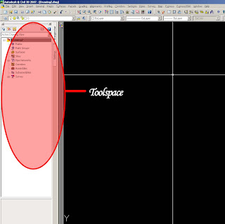
- If your Toolspace is not already open, open it from the menu General > Show Toolspace…
- In Civil 3D interface, click on Map > Query > Define Query…
- In the Define Query window, click on Drawings and click Attach.
- You can browse directly to the folder containing your drawing, or you can use aliases.
Note: Using Aliases
Aliases in Autodesk Map is a shortcut to your folder. This is extremely useful when you need to access a folder in Autodesk Map often.To create an alias:
- Click the Create/Edit Aliases icon.
- In the Drive Alias field, type in a name to identify the folder you wish to create a shortcut to. The name must not have any spaces in between.’
- Click Browse and browse to the folder you wish to create a shortcut to. Click OK.
- Click Add. You should see your new alias in the box above.
- Click Close when you are done.


- In the upper panel, select the drawing which contains the text values which you want to convert into 3D points. Click Add. You should see the file added in the lower panel.

- Click OK. The drawing name will be attached in your Toolspace.

Before you start converting your data, first you need to filter out all information to ensure that only the text values containing the relevant elevation data will be converted. You wouldn’t want text containing words like “Tree” or “School” in your point database! To filter out the data, you would be using Queries.
- In Civil 3D interface, click on Map > Query > Define Query…
- In the query window, filter out the data by using the options under Query Type.

- Typically, Property is used as the text values are often placed on a separate layer. Click Property.
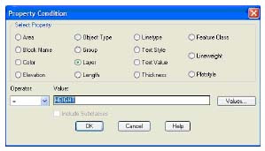
- In the Property Condition dialog window, click the Layer radio button. In Value, you can type in the layer name, or you can select from a list. Click the Values button. You will see a list of all the layers from your attached drawing, from which you can highlight. To select more than one layer, hold down the Ctrl button while you click on the layer names. Click OK.

- Check the information, and click OK.
- Before running the conversion, run a quick check to ensure that all the data has been filtered properly. Under Query Mode, click Preview, and then click Execute Query. (Note: If you select OK, nothing will happen as it will merely save the query settings; it does not actually run the query)

- You will see a preview of all the data in your drawing. You can still zoom and pan the drawing to view the data, but if you redraw, the data will disappear. Take a look at your drawing to make sure that the data has been properly filtered.
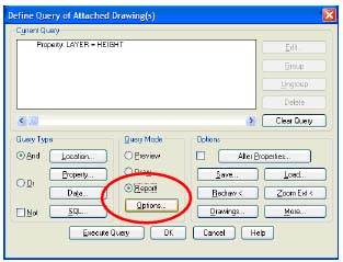
- Once you have verified that the data has been filtered properly, you can run the conversion now. Go back to the Query window.
- Without modifying the query settings, under Query Mode, select the Report radio button, and click Options.
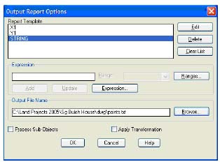
- This is where you specify your report template, i.e. your XYZ file. Click Expression.

- In the Report Template Expression window, open the Properties tree. Scroll downwards until you see X1. Highlight it and click OK.
- Click Add. You should see .X1 added in the top panel.

- Repeat the above steps to add Y1.
- For the last column, don’t select Z1! This is because the Z-value in the drawing is 0. Instead, you would be making use of the text value as the elevation. Repeat the above steps to add STRING.
- Click the Browse button, and type in the name of the XYZ file you are going to generate.
- Click OK, and then click Execute Query. The XYZ file will be generated.
- You can check your file by opening it from Windows Explorer.

- To import the points, go to the menu Points > Create Points > Import Points.

- Under Format, select ENZ (comma delimited) from the drop-down list.
Note:
The drop-down list contains a list of standard file formats in Autodesk Land Desktop. You can easily create your own format if you need to.
P = Point Number
N = Northing
E = Easting
Z = Elevation
D = DescriptionComma delimited means the columns are separated by commas, whereas space delimited means the columns are separated by spaces.
- Under Source File, click the open icon, browse to the folder containing your XYZ file, and select the file.
- Check the Add Points to Point Group, and click the blue icon on the right. Create a point group named Existing. This is to make it easier for you to create your existing ground surface later. By naming your point group Existing, you will know that all the points in this group are meant for your existing ground surface.

- Click OK.
- The points will be imported into the drawing.


8 comments:
This is a very good tip clean, instead of fighting with the surveyor for the data damp this is a lot easier and fast.
Thanks
Its a LOT simpler and quicker and more accurate to use TopoGX.
All you need do is press the 2D to 3D convert toolbar button, then press the big "Convert Now" button. The conversion is done in a few seconds and automatically converts your Text levels to Z levels and inserts them at the visually associated insertion cross, whether it be a Point entity or block insert.
Its also got great features like a really easy 3D Viewer, instant Surface Contours, Surface Height colouring, Flow Arrows, Longsectioning and I think they mentioned that they will be added Voluming soon!
Sorry, forgot to mention, TopoGX automatically uses your 2D survey lines as constraints so Ditches, roads and any other surveyed features stand out cleanly.
bonetiberiu@gmail.com
i managed to create the txt file but i receive the "error parsing value" when importing. do you have any idea what i did wrong?
thanks!
hey ive been trying to do this with civil 3d 2010, but i just cant find the comands you mention, can you do an update for the new version?
A reply to "bonetiberiu@gmail.com ":
Another reason why the "parsing error occurs" is because of the Text Encoding format. Try so "save as..." the text file using ANSI encoding instead of UNICODE. You can search the options on the "save as..." window. Simple as that. Everything will work just fine.
mandaldyis@yahoo.com
Reply to Diego Delgado-Elias,
Under Customizations in All Files, scroll to Open > "C:\Documents and Settings\user name\Application Data\Autodesk\C3D 2010\enu\Support\MapClassic.cuix"
Then click APPLY. The map menu should appear and you can follow the same steps as mentioned in the post.
After reading the reply about the "error passing value"
I still can´t find where to change the text encoding format (UNICODE to ANSI). need some help.
Thanks
Post a Comment