

To account for those bends, I'd define the right and left banks for the river/stream that I am working on. In most cases, the surveyor would have already defined it either by using spline or polyline.
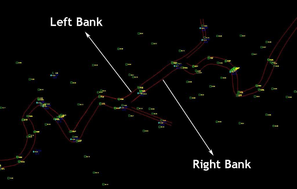
Make sure the polylines are joined and if it’s a spline, convert it to polyline.

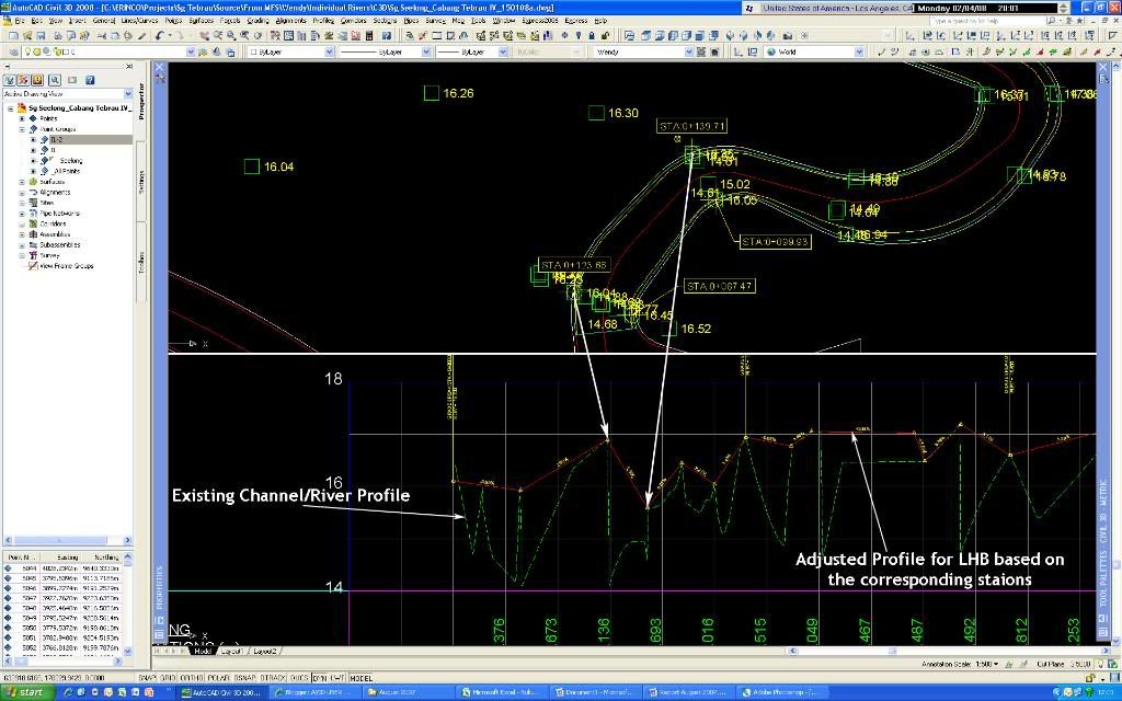
Once, that is done, convert the left and right polyline to alignment. Create profiles for the two alignments. In order to create profile for the left/right bank, label the alignment at the location where the survey has been carried out to display the station/chainage information. Likewise, define a centreline alignment (CL) for the river and create profile using the same method as alluded to earlier. Create two horizontal viewports. One showing the plan and the other showing the profile. Then, create the profile based on the levels and corresponding stations/chainages shown.
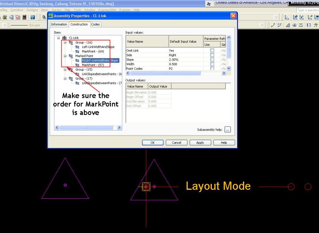
I used a combination of MarkPoint and LinkSlopeBetweenPoints for the assembly. First, insert the LinkWidthAndSlope. Put dummy values for the width and slope since it’ll be controlled by the alignment and profile. Set the omit link to YES. Secondly, add the MarkPoint. Set a name for it, in this case, LEFT. Repeat the same for the right side of the assembly. The assembly should look like this:
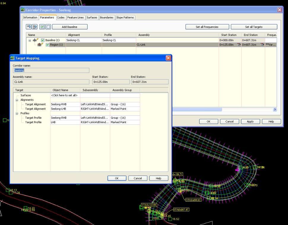
 For the corridor, base alignment and profile would be the river CL. Then, set the left target alignment and profile to the left bank alignment. Do the same for the right as shown:
 The finished corridor should look like this:
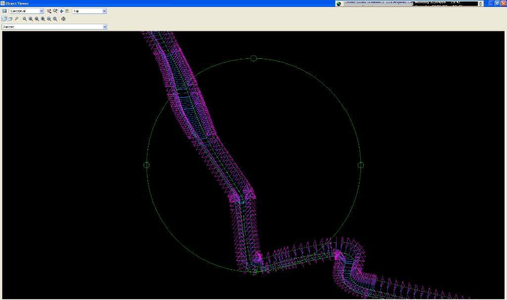 If there are better ways to do it, do let me know.... :-)

3 comments:
Nice post, Wendy.
gosh, this blog is confusing for an ordinary people like me. Salam from Indonesia.
Arry
Post a Comment